Microcontroller Powered Motor Controller
A 8051 based microcontroller programmed in C. Team Project
Developing a servo DC motor speed controller was a challenging yet rewarding engineering project that combined hardware integration, embedded programming, and control system design. The objective was to create a closed-loop system capable of regulating the speed of a DC motor with real-time feedback, using an 8051 microcontroller. The completed system effectively demonstrated precise speed control while displaying the motor’s RPM on a 3-digit 7-segment display.
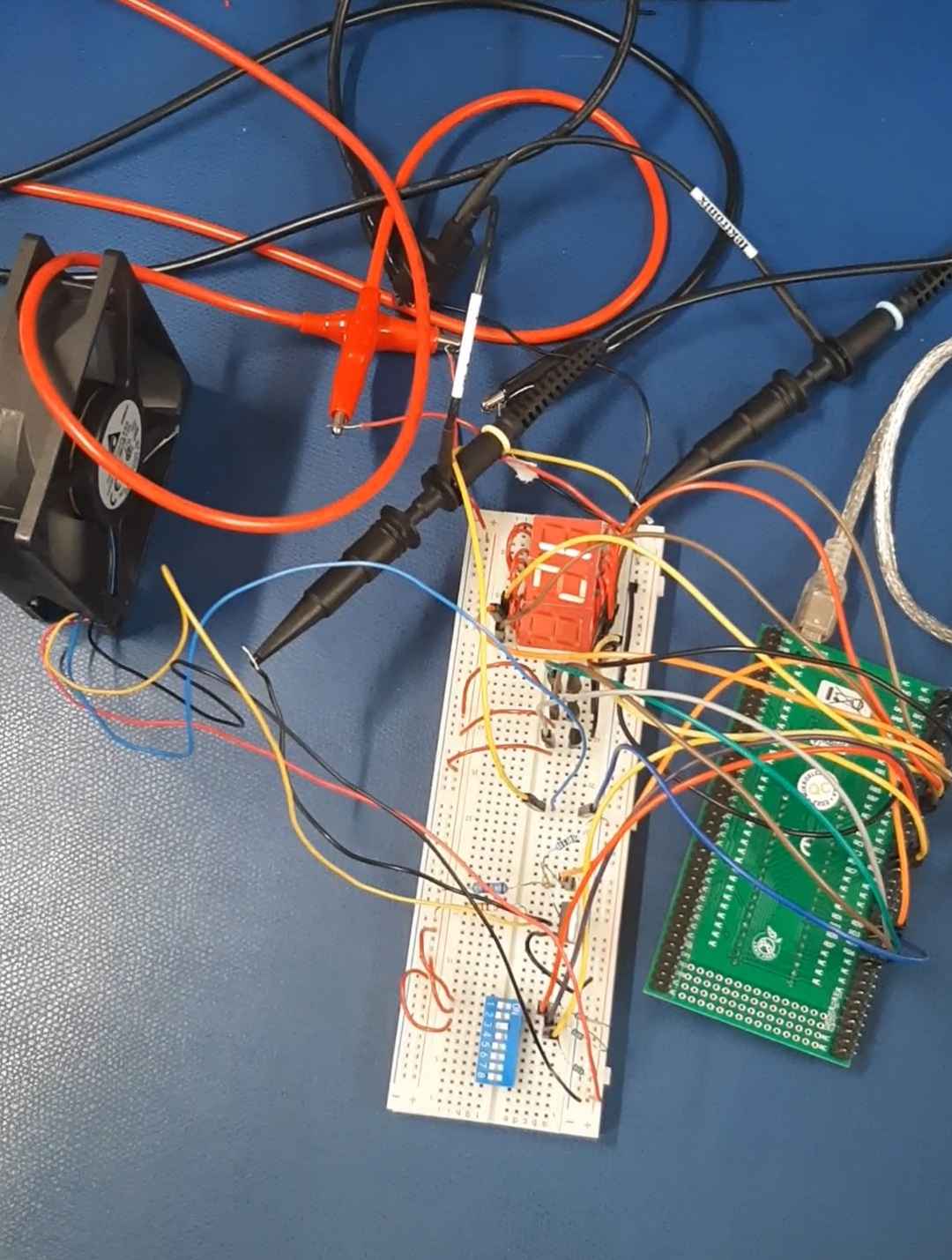
Project Objective and Challenges
The primary goal was to design and implement a robust closed-loop feedback system capable of:
- Input Management: Accepting user-defined target speeds via a DIP switch interface.
- Speed Measurement: Accurately measuring motor speed using encoder feedback.
- Feedback Control: Using a proportional control loop and PWM (Pulse Width Modulation) to adjust motor speed.
- Real-Time Display: Providing clear speed visualization on a 7-segment display.
Achieving these goals required careful consideration of both hardware and software integration, with particular emphasis on synchronization and responsiveness in the control system.
System Design
Logic Implementation
At the heart of the system was the 8051 microcontroller. A PWM signal was employed to control the motor’s speed, with the duty cycle dynamically adjusted based on encoder feedback. This adjustment mechanism was managed by an interrupt-driven feedback loop, ensuring real-time corrections to match the target speed.
Hardware Integration
The encoder provided speed data, sending pulses to the microcontroller via pin P3.2. These pulses were processed at 50 ms intervals, governed by Timer1 interrupts, to compute RPM. The calculated RPM was then compared to the desired speed, and adjustments were made by varying PWM signal that was being sent to the motor’s MOSFET on pin P3.0.
Display System
The real-time RPM was displayed on a 3-digit 7-segment display, connected to Port P1 of the microcontroller. To optimize port usage, multiplexing was implemented using MOSFETs controlled by pins P3.5, P3.6, and P3.7. The display operated in a time-sharing manner, cycling through the thousands, hundreds, and tens digits at a frequency imperceptible to the human eye.
Results and Insights
We found that large oscillations in the speed of the motor on our first implementation of the RPM calculation and P-loop system. We improved the system by adding a larger shift register that would be able to look at the same time frame of data but be able to do calculations on it much faster. We also improved the efficiency of the code by running only the code that was needed at the time. The speed of the of the RPM and P-loop calculation was increased by a factor of 10 resulting in very small oscillations and a very low error.
The final system successfully achieved all our goals. The closed-loop feedback mechanism effectively synchronized motor speed with user-defined targets, minimizing error through proportional control. The real-time RPM display provided clear and accurate feedback, showcasing the system’s functionality.
This project underscored the importance of integrating hardware and software in embedded systems. Developing the PWM control logic, processing encoder feedback, and synchronizing these elements with the display system required meticulous planning and execution.
Key Challenges
One of the most complex aspects was ensuring accurate and stable speed control. The speed of the PWM adjustments were critical for achieving smooth motor operation. Implementing interrupts to handle real-time events proved essential for resolving these challenges.
Processing the encoder signals to calculate RPM also presented a significant learning curve, as it required a detailed understanding of signal processing principles and interrupts within the constraints of a microcontroller.
Conclusion
The servo DC motor speed controller project demonstrated the practical application of embedded system principles in solving real-world engineering challenges. By leveraging the capabilities of the 8051 microcontroller, the system achieved a high degree of precision in motor control and real-time feedback.
This experience not only solidified my understanding of microcontroller programming and control system design but also my circuit design experience.
#include <reg51.h>

unsigned int lookUpSpeed(unsigned int);
unsigned int lookUpChar(unsigned int);

sbit PWM = P3^0;

sbit display1 = P3^5;
sbit display2 = P3^6;
sbit display3 = P3^7;

unsigned int Power = 0;
unsigned int Input = 0;
unsigned int Speed = 0;

unsigned int edgeCount = 0;
unsigned int timerCounter = 0;
unsigned int RPMsample1 = 0;
unsigned int RPMsample2 = 0;
unsigned int RPMsample3 = 0;
unsigned int RPMsample4 = 0;
unsigned int RPMsample5 = 0;
unsigned int RPMsample6 = 0;
unsigned int RPMsample7 = 0;
unsigned int RPMsample8 = 0;
unsigned int RPMsample9 = 0;
unsigned int RPMavg = 0;
unsigned int show = 0;

//Look up table for converting dipswitch input from 0-8 to 0-100% speed
unsigned int lookUpSpeed(unsigned int num)
  {
  switch(num){
    case 0: num = 0; break;     //0 RPM
    case 1: num = 1; break;     //240 RPM
    case 2: num = 3; break;     //720 RPM
    case 3: num = 4; break;     //960 RPM
    case 4: num = 5; break;     //1200 RPM
    case 5: num = 7; break;     //1680 RPM
    case 6: num = 8; break;     //1920 RPM
    case 7: num = 10; break;    //2400 RPM
  }
  return num;
}

//Look up table for seven segment display
unsigned int lookUpChar(unsigned int num){
  switch(num){
    case 0: num = 0xC0; break;
    case 1: num = 0xF9; break;
    case 2: num = 0xA4; break;
    case 3: num = 0xB0; break;
    case 4: num = 0x99; break;
    case 5: num = 0x92; break;
    case 6: num = 0x82; break;
    case 7: num = 0xF8; break;
    case 8: num = 0x80; break;
    case 9: num = 0x90; break;
  }
  return num;
}

//Delay function
void MSDelay(unsigned int time) {
  unsigned int i, j;
  for(i = 0; i < time; i++) {
    for(j = 0; j < 120; j++) {
      // Do nothing
    }
  }
}


//Encoder interupt
void falling_edge_interrupt() interrupt 0
{
  edgeCount++;
}

//Timer Interupt
void Timer1() interrupt 1
{
  // Calculate Rotations Per Minute (RPM) based on the number of pulses (edges) detected:
  // 1. Calculate pulses per second by counting edges in a 50-millisecond interval and doubling.
  // 2. Multiply pulses per second by 60 to get pulses per minute (PPM).
  // 3. Assuming 1 pulses per rotation, calculate RPM by dividing PPM by pulses per rotation (PPR).
  // 4. The final RPM is obtained by divided by the period of measurement, 50x10^-3.
  // Summary Equation: RPM = edgeCount * 60.

  //Shift register to calculate a rolling average of RPM
  RPMsample1 = (edgeCount)*6*10;
  RPMavg = (RPMsample1+RPMsample2+RPMsample3+RPMsample4+RPMsample5+RPMsample6+RPMsample7+RPMsample8+RPMsample9)/9;
  RPMsample9 = RPMsample8;
  RPMsample8 = RPMsample7;
  RPMsample7 = RPMsample6;
  RPMsample6 = RPMsample5;
  RPMsample5 = RPMsample4;
  RPMsample4 = RPMsample3;
  RPMsample3 = RPMsample2;
  RPMsample2 = RPMsample1;

  edgeCount = 0;


  //Get input from dipswitch, calculate speed and error and use a P-Loop to set power to the motor

  Input = P2; //input from dipswtich
  Speed = lookUpSpeed(Input); //convert 3 bit to %speed

  Speed = 24*Speed; //0-10 to 0-2400RPM

  Power = (Speed-RPMavg)*0.3; //error

  if (Speed < RPMavg){
    Power = 0; //clamping at 0
  }
  if (Power > 10){
    Power = 10; //clamping at 10
  }
  show = RPMavg;

  TH0 = 0x4B;         // TH1: Timer 1 High Byte set for 50ms Interrupt
  TL0 = 0xFF;         // TL1: Timer 1 Low Byte set for 50ms Interrupt
  TF0 = 0;         // TF1: Timer 1 Overflow Flag (cleared)
  TR0 = 1;         // TR1: Timer 1 (start Timer 1)
}

void main(){

  P1 = 0x00; //display
  P2 = 0x00; //input

  PWM = 0;
  display1 = 0;
  display2 = 0;
  display3 = 0;
  Speed = 0;

  IT0 = 1;         // Configure Interrupt 0 for falling edge on /INT0 (P3.2)
  EX0 = 1;         // Enable EX0 Interrupt

  TMOD &= 0xF0;    // Clear 4-bit field for timer0 (preserving existing config)
  TMOD = 0x11;     // Timer Mode: T1 in mode 1 for 50ms interrupt, T0 in mode 1 for timer0 (0001 0001)
  TH0 = 0x4B;      // Counting from 0x4BFF to 0xFFFF takes 50ms. After 50ms, Interrupt routine is called.
  TL0 = 0xFF;
  TR0 = 1;         // Turn on Timer 1
  ET0 = 1;         // Enable Timer 1 interrupt

  EA = 1;          // Enable Global Interrupt Flag to Start Interrupt

  while(1){
    //PWM Control
    PWM = 0x00;
    MSDelay(1*Power);
    PWM = 0xFF;
    MSDelay(1*(10 - Power));

    //seven segment switching
    if (display1 == 0 && display2 == 0){            //3 high
      display1 = 1;
      display2 = 0;
      display3 = 0;
      P1 = lookUpChar((show%10)/1);
    } else if (display2 == 0 && display3 == 0){     //1 high
      display1 = 0;
      display2 = 1;
      display3 = 0;
      P1 = lookUpChar(show/100);
    }else{                                          //2 high
      display1 = 0;
      display2 = 0;
      display3 = 1;
      P1 = lookUpChar((show%100)/10);
    }
  }
}