
Bison GPS Tracking Collar
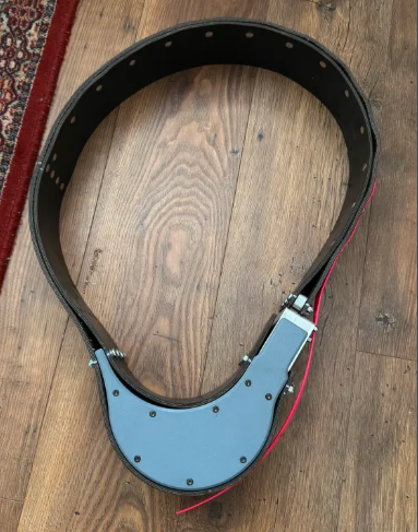
Design and prototyping of a wallowing-resistant, self-releasing GPS tracking collar for long-term bison monitoring. Team Project
Project Overview
This project was a year-long capstone focused on designing and prototyping a rugged GPS tracking collar for bison herd monitoring.
Existing commercial collars fail prematurely due to extreme mechanical abuse, environmental exposure, and limited battery life. The goal was to develop a collar capable of surviving multiple years in harsh field conditions while reliably transmitting GPS data via satellite.
The project was sponsored by Wright Collars and conducted as part of MSE 410/411 at Simon Fraser University.
My Role
I was responsible for the electrical and firmware design, including:
- Microcontroller selection and low-power firmware architecture
- Satellite communication integration (ARGOS / Kinéis)
- GPS integration and validation
- Power management and battery life analysis
- PCB design, bring-up, and debugging
System Architecture
The collar integrates multiple subsystems into a compact, sealed enclosure:
- Low-power microcontroller (LPC802)
- GPS module for position acquisition
- ARGOS satellite transmitter for global data relay
- Servo-actuated mechanical drop-off mechanism
- Primary lithium battery pack designed for multi-year life
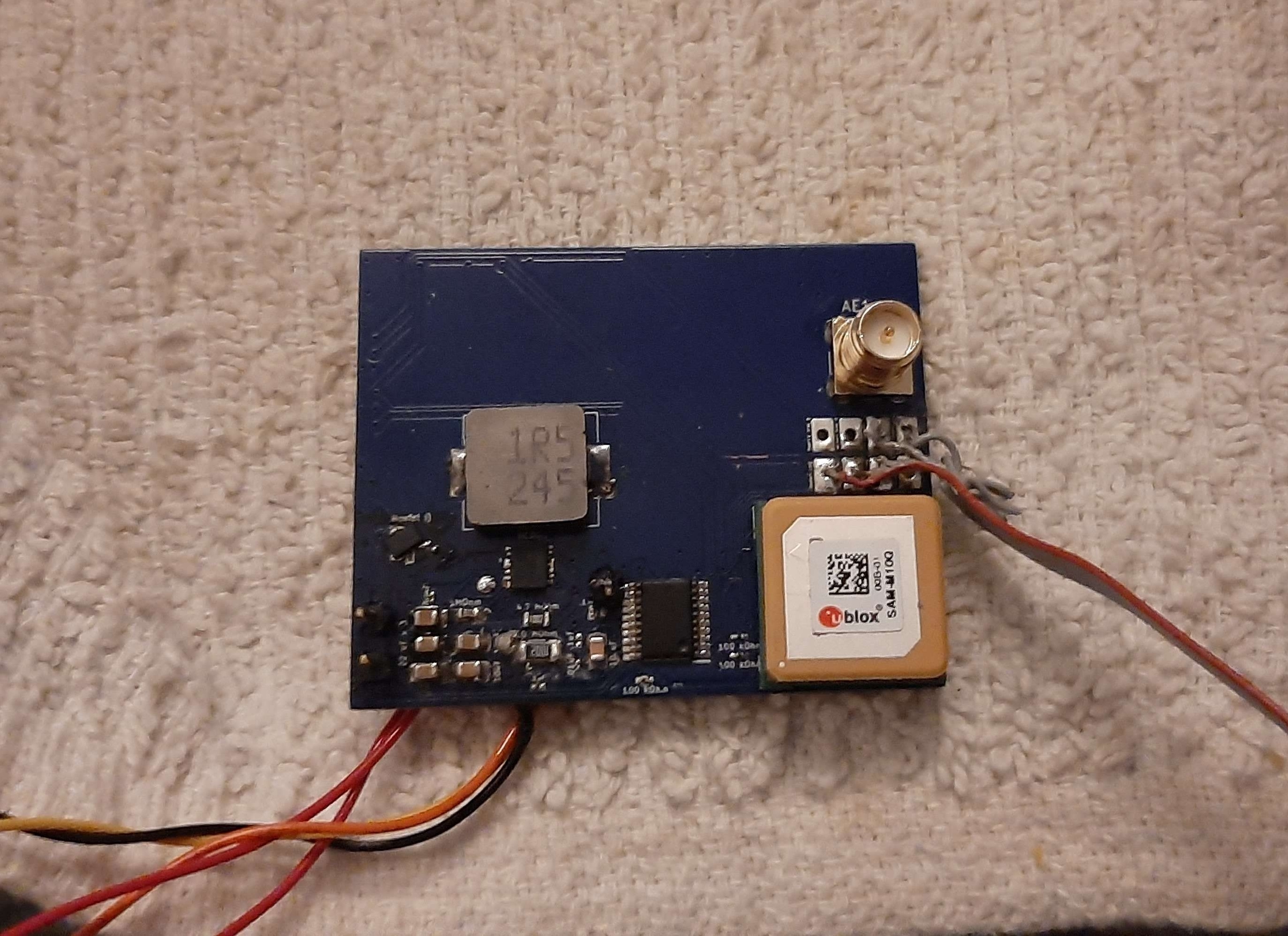
All electronics were mounted on a custom PCB and enclosed within a rugged housing designed to survive impact, mud, water ingress, and extreme temperatures.
Key Engineering Challenges
1. Extreme Mechanical and Environmental Constraints
The collar had to survive behavior unique to bison: wallowing in mud, rubbing against trees, impacts, and long-term exposure to water, dust, and freezing temperatures.
This drove strict requirements on enclosure sealing, connector elimination, and mechanical robustness. All electronics had to tolerate shock, vibration, and contamination without service access.
2. Multi-Year Power Budget
Achieving a multi-year lifespan required aggressive power optimization.
Key challenges included:
- Deep-sleep firmware design
- Minimizing GPS acquisition time
- Managing high peak currents during satellite transmission
- Designing battery measurement circuitry without excessive quiescent draw
Real-world current measurements revealed issues not visible in simulation, including ADC loading effects that required hardware redesign.
3. Reliable Satellite Communication
The system uses the ARGOS satellite network, which trades bandwidth for lower power consumption.
Challenges included:
- UART-based communication with the satellite module
- Strict timing and power constraints during transmission windows
- Validating transmission reliability under limited test access
Development was performed using evaluation hardware, with provisions added for future integration of production modules.
Mechanical
A servo-actuated, seatbelt-style drop-off mechanism was developed to allow the tracking collar to release automatically at end-of-life or under predefined fault conditions. Because the collar operates unattended for long durations and may be under significant mechanical load, the release mechanism had to be both electrically efficient and mechanically robust.
From an electronics and systems perspective, the drop-off integration imposed several strict requirements:
- Control the servo without any idle current draw during normal operation
- Guarantee a successful release even while the collar is under high tensile load
- Remain mechanically stable under shock, vibration, and environmental exposure
Meeting these constraints required close coordination between mechanical design and electrical control. The servo is only powered during the release event, eliminating standby losses while still providing sufficient torque to disengage the locking mechanism when commanded.

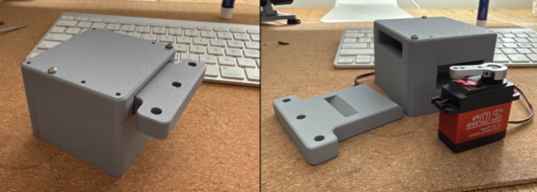
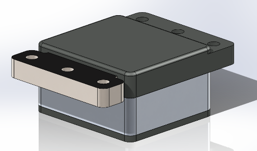
To validate the design before committing to a machined assembly, a 3D-printed prototype was produced and instrumented for functional testing. This allowed rapid iteration and early identification of mechanical weaknesses.
Here is an example of the prototype functioning under load:
The prototype was subsequently tensile tested to failure to characterize its load limits and identify failure modes. The locking mechanism failed at approximately 200 lbs of applied load, at which point the locking pin sheared.
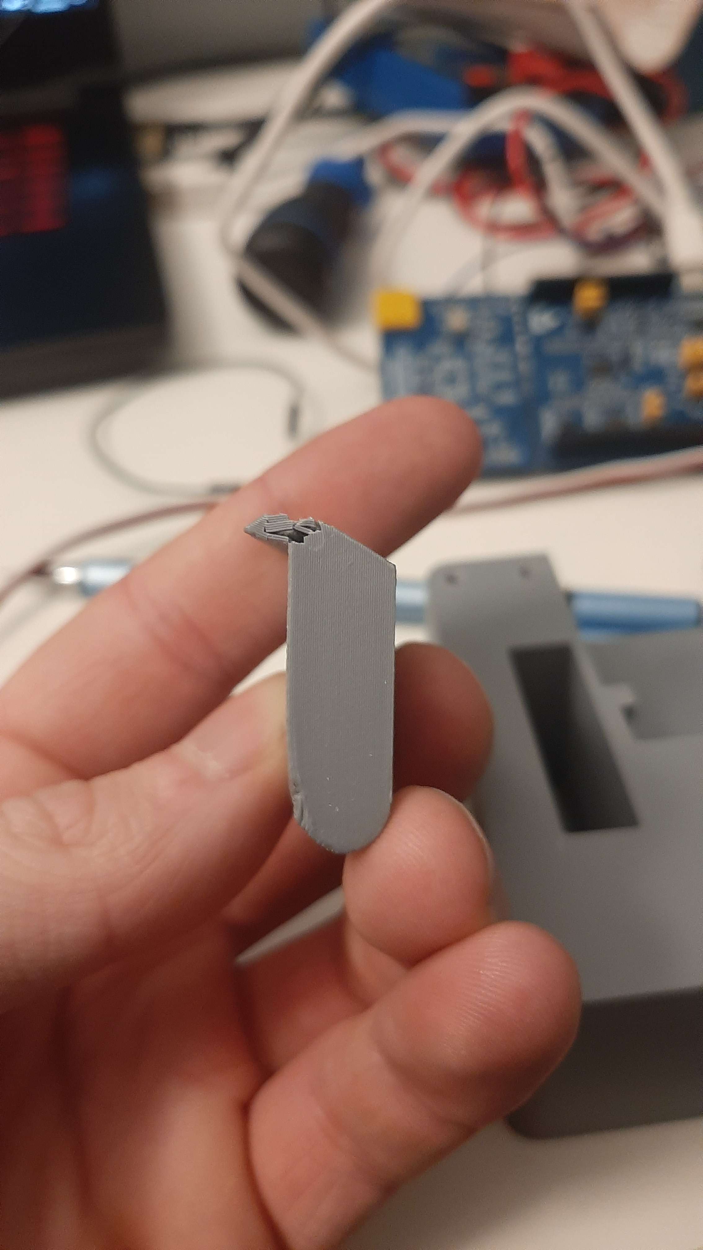
Post-failure analysis showed that the printed enclosure supporting the locking pins deflected under load, concentrating stress at the end of the pin rather than distributing it across the mechanism. This insight directly informed the next design revision, where additional fasteners and structural reinforcement were added to reduce enclosure deflection at this critical interface.
Identifying this failure mode through controlled testing provided confidence in the revised geometry and justified transitioning the design to a machined aluminum version for the final assembly.
The final assembly was tested to ~400lbs without failure. It also went through thorough impact testing
Electrical
Battery Voltage Sensing and ADC Limitations
Battery voltage monitoring proved more challenging than initially expected.
Due to the battery voltages potentially being higher than the ADC range, a resistor divider was used to keep the voltage in range.
To minimize quiescent current draw, the voltage divider resistors were chosen with very large values. While this reduced static power consumption, it introduced an unintended side effect: the ADC input impedance was not high enough to reliably sample the divided voltage.
As a result, the ADC measurement node effectively floated, producing unstable and inaccurate readings that did not reflect the actual battery voltage.
This issue highlighted a key trade off in low-power design: minimizing static current must be balanced against the electrical requirements of the measurement circuitry. In hindsight, a buffered measurement or a switched voltage divider would have been a more robust solution.
Unexpected Current Consumption
Measured current consumption differed from initial estimates based on component datasheets and calculation.
While average current draw met the long-term power budget, several transient behaviors significantly impacted energy usage, including wake-up current spikes, GPS acquisition behavior, and satellite transmission overhead.
These effects are summarized in the project poster, which presents measured current draw across different operating modes. This experience reinforced the importance of real-world measurements over purely theoretical power models, especially for systems targeting multi-year lifespans.
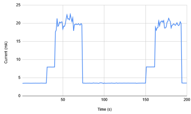
The current consumption shows idle current, microcontroller on and GPS on current. Due to supplier delays, we did not get a satellite transmission module in time to test.
Software
Embedded Software Architecture
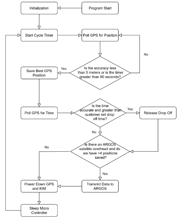
The system is designed for ultra-low power operation. All components remain in sleep mode by default, with the microcontroller waking periodically to acquire GPS coordinates and then returning to sleep. Once a configurable number of data points is collected, the system transmits the data via satellite. Both GPS sampling rate and transmission frequency are customer-configurable to balance battery life and data resolution.
Communication between the host microcontroller, GPS module, and satellite modem is handled over UART. GPS and satellite modules are placed into low-power states between operations to minimize energy consumption while preserving RAM for fast wake-up.
Satellite Communication
Satellite transmission is controlled by a timing mechanism referencing the previous transmission, a configurable transmission interval, and a satellite visibility check. Collected GPS data is buffered in RAM and transmitted to the ARGOS satellite network on demand by the host microcontroller.
Data is encoded in a compact binary format and sent as a hexadecimal string to minimize RAM usage and reduce transmission time, directly improving battery life.
GPS Control
The GPS subsystem operates on a configurable sampling interval and is optimized for fast warm starts and high positional accuracy. The module remains in a low-power state between fixes while retaining RAM to reduce acquisition time.
Battery Management & Power States
Power consumption is actively managed by disabling the GPS and satellite modem when idle and placing the microcontroller into power-down mode while retaining RAM and program state. Battery voltage is measured via the onboard ADC during satellite transmission to capture worst-case load conditions. If voltage drops below a critical threshold, the system triggers an emergency collar release and sends an alert transmission.
The system is designed to operate across harsh environmental conditions (-40 °C to 40 °C) and achieve a multi-year operational lifespan.
Data Encoding Format
Each transmission consists of a single hex string containing multiple packed data fields, including:
- GPS Time of Week
- Latitude and Longitude (scaled integers)
- Horizontal accuracy estimate
- Battery voltage
Using raw binary encoding significantly reduces memory usage compared to human-readable formats such as ASCII, enabling longer deployment durations between transmissions.
System Validation and Data Visualization
Validating the end-to-end system was a major challenge.
Once GPS and satellite transmission were operational, data had to be decoded, stored, and interpreted in a meaningful way. To support this, we developed a simple web-based interface that displays received GPS points on a map.
Seeing the final output of a continuous track of location data visualized geographically was a critical milestone. It confirmed not only that individual subsystems worked, but that the full pipeline from sensor acquisition to user-facing data presentation was functional.
Images of the final map output and the data visualization interface are included to demonstrate this end result.
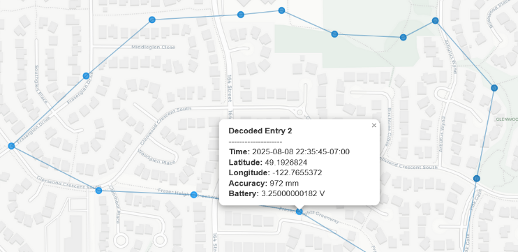
Extensive testing was done by hiking with the collar and checking to make sure the data was valid.
Results
The final prototype demonstrated:
- Reliable GPS acquisition and satellite transmission
- Stable low-power operation with predictable energy usage
- Successful actuation of the drop-off mechanism under load
- Mechanical resilience to impact, dirt, and water exposure
Documentation
A more in depth report on the process and analysis of of results is avalible in the final capstone report and user manual.